The frame-type RBTR distribution LV switchboard was originally developed as a switching system for mounting in concrete transformer station structures. Its instruments and use cover part of the function of the RST series and part of the RDR 1000 basic series (Ref. separate catalogue). It is a specific switchboard used a specific segment of customers. However, the RBTR switchboard features some specific attributes that can correspond to general requirements.
Technical data:
Rated voltage: 3 x 400 / 231 V; 50 Hz
Rated current: up to 630 A / up to 1000 A
Short-circuit capacity: at least 20 kA / at least 35 kA
Protection against electric shock: automatic disconnection from the power source
Protection degree: IP 20 from the front side
Surface treatment: powder technology
Technical description:
The RBTR switchboard consists of the supporting frame, doors, covers and instruments.
Frame:
The frame is made of cross-members, webs and jibs (made of 3 mm steel sheet). The main circuit breaker, its connection space and spaces in the upper part of the frame are covered with doors from the front side (made of 2 mm steel sheet), and with covers from above and from the side (made of 1.5 mm steel sheet). The frame does not contain webs like RDR 1000 switchboards.
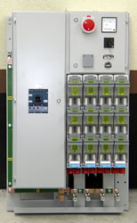
Typical instruments installed in the switchboard assembly
The main protective element of the RBTR switchboard is a “non-withdrawable” circuit breaker (up to 630 A or up to 1000 A; also fused switch disconnector can be installed at the upstream side). The switchboard outlets are equipped with fused switch disconnectors for rated currents of up to 400 A, sorted one below the other that can be withdrawn from the frame. The electrical current is measured using an indirect measurement method, using 3 withdrawable current instrument transformers and A-meters (analogous instrument with a dragged on pointer), or an EAM1 electronic A-meter or a SMZ 33 measuring and registration instrument (to measure the following quantities: U, I, cos φ, kW, kVA, kVAr, frequency, 15 minutes maximum). The voltage can be measured using a V-meter with changeover switch. On request a testing terminal board can also be installed (the switchboard width, however, is limited), and a place can be prepared in advance for the installation of consumption meters for the purpose of invoicing. The switchboard can be equipped with 400 V and 231 V sockets, and with an outlet for the lighting of the switching station. Measuring and auxiliary circuits are protected with cylindrical fuses and circuit breakers. Furthermore, the sockets can also be protected with residual current circuit breakers. The outlet from the main circuit breaker or the fused main switch disconnector is sometimes provided with lightning arresters. Two switchboards may be arranged together to form a set with power fed from two points, and with a bus coupler. Parallel operation is excluded for such an arrangement because of the dimensioning of the main busbars that are capable of withstanding only currents equal to the rated current of the main circuit breaker.
Downloads
- Catalog RBTR (pdf, 1,9 MB)
References
- ABB – switchboards for administrative complex
- Campus Square Brno
- Orlí Street Theatre
- Moravian Provincial Archive Brno
Contact persons
T +420 515 502 503
M +420 606 789 318
E obchod@esb-rozvadece.cz
E marketa.otoupalova@esb-rozvadece.cz